portable screw air compressor LGCY Operating instructions second page
June 28, 2024
Please visit the Operation Mannual First Page
Chapter 2, Construction and Operating Principles
1, Architecture and system flow
1.1, Machine construction (omitted)
1.2, System flow: main air system, control air system, oil system
1.2.1, Main airway system
The main air circuit system consists of air filter, air inlet valve, screw mainframe,
oil-air separator (including oil
separator core), minimum pressure valve and so on.
Outside air through the air filter to filter out dust, impurities, through the air inlet
valve into the screw host
suction chamber, and in the compression process and the injection of lubricating oil
mixing. After compression, the
oil-air mixture is discharged into the primary oil-air separator (oil-air barrel), more
than 99% of the oil is separated
off, and then after further separation by the secondary oil-air separator (oil separator
core), the clean compressed air
passes through the minimum pressure valve and enters into the use system.
A. Air filter
The air filter is a dry paper filter with a pore size of about 10um. Its main function
is to filter the dust in the air.
B. Air intake valve
The air inlet valve is of disc type, through the opening, half-opening and closing
degree of the disc, it can realize
the adjustment of the air inlet (i.e. exhaust volume) to achieve the purpose of energy
saving.
C. Screw host
With the rotation of the rotor, the size of the tooth groove space formed by the
negative and positive rotors changes,
completing the inhalation, compression and discharge of air. At the same time in the
compression, lubricating oil is
also sprayed into the compression chamber due to pressure difference and mixed with air,
and discharged to the oil and
gas separator together.
D. Oil-air separator
In order to reduce the oil content in the exhaust (i.e. reduce oil consumption) and
recycle the lubricating oil in the
unit, it is necessary to utilize the oil-air separator. From the host of the oil and gas
mixture into the primary oil
and gas separator (oil and gas barrel), the use of mechanical collision method, the
separation of the vast majority of
the lubricating oil; and then, the oil content has been greatly reduced oil and gas
mixture at a lower rate of flow into
the secondary oil and gas separator (oil sub-core), the use of affinity agglomeration
method, and further separation of
residual lubricants.
E. Minimum pressure valve
The cleaner compressed air after separation is fed into the system through the minimum
pressure valve. The opening
pressure of the minimum pressure valve is set at about 0.45Mpa, which mainly has the
following functions:
(1). Priority is given to the establishment of circulating pressure required for
lubricating oil when starting to ensure
the lubrication of the machine.
(2). When the gas pressure of the oil and air tank exceeds 0.45Mpa, the valve will be
opened only after the oil and air
tank is opened, which can reduce the air flow speed through the oil separator core, in
addition to ensuring the
separation effect of the oil separator core, and protect the oil separator core from
being damaged due to the large
pressure difference.
(3). Check function: When the pressure in the oil and gas barrel drops after stopping
the machine, it can prevent the
compressed air in the pipeline from flowing back.
1.2.2, Control airway systems
The control air system consists of load and unload switching valve (solenoid valve),
proportional valve, bleeder valve,
air inlet valve servo cylinder and safety valve.
A. Load and unload switching valve (solenoid valve)
Loading and unloading switching valve is a solenoid valve controlled by a manual switch
for loading/unloading switching.
Load reduction at startup and before shutdown, loading during working hours, the machine
relies on the proportional
valve to fully automatically regulate the operation.
B. Proportional Valve
Proportional valve is the regulator, is the key component of the pressure control, it
converts the working pressure
(input pressure) into control pressure (output pressure), the output pressure of the
output pressure determines the
expansion and contraction of the two servo cylinders.
C. Inlet valve servo cylinder
Servo cylinder is the actuator. The intake valve servo cylinder controls the opening of
the intake valve disc according
to the level of the proportional valve output pressure, thus controlling the intake
volume.
D. Bleeder valve
Bleeder valve is installed in the minimum pressure valve after the use of the system
pipeline, it is also subject to the
control of the proportional valve output pressure, the appropriate time to the
atmosphere to discharge, reduce the
excessive system pressure.
E. Bleeder valve
The air release valve is installed after the oil separator core and before the minimum
pressure valve, it is also
controlled by the output pressure of the proportional valve, and it will be released to
the atmosphere at the right time
to gradually reduce the pressure in the oil and gas tank.
F. Safety valve
Safety valve is to ensure the safe operation of the machine parts, under normal
operating conditions do not act. If the
safety valve continuous action, you should promptly check the reasons (such as air inlet
regulation failure, diesel
engine throttle regulation failure, etc.), and promptly exclude. For large displacement
compressor, if the system gas
consumption is suddenly reduced to zero, the pressure may rise faster than the reaction
speed of the pneumatic
adjustment, so that the safety valve opens to relieve pressure.
The safety valve has been adjusted at the factory.
The method of checking the safety valve is to gently pull the air release lever on the
safety valve when the compressor
is working at full capacity, if the safety valve can discharge air to the outside at
this time, it will be regarded as
normal.
1.2.3, Oil system
The oil circuit system without oil pump, the lubricating oil relies on the pressure
difference between the compressor's
discharge port and the host's oil injection port to maintain the flow in the circuit.
When the machine is running, the
lubricating oil in the oil and gas barrel under the action of differential pressure,
through the temperature control
valve into the oil cooler, cooled and then through the oil filter to remove impurities
particles, most of the
lubricating oil is sprayed into the compressor compression chamber, and the rest of the
lubricating oil were passed to
the bearings, shaft seals, etc., to play a role in lubrication, sealing, cooling, noise
reduction, and so on. Finally,
all the lubricating oil with the compressed gas is discharged into the oil and gas
barrel, separating out the vast
majority of the lubricating oil for recycling. The small amount of lubricating oil
separated from the oil separator core
is also led back to the suction port of the compressor and other low-pressure
places.
A. Oil cooler
The oil cooler cools the circulating lubricating oil. The fins of the oil cooler are
easily covered by dust, which
affects the cooling effect and may lead to high exhaust temperature and shutdown, so it
should be blown and cleaned
every once in a while to ensure its cooling effect.
B. Oil Filter
The oil filter is a paper filter whose function is to remove impurities in the oil, such
as metal particles, oil
deterioration, etc., to protect the bearings and the normal operation of the rotor. Its
filtration precision is between
10μ~15μ. The oil filter is a disposable consumable, if the oil filter is clogged and not
replaced in time, it may lead
to insufficient oil intake, increased head exhaust temperature, resulting in shutdown;
at the same time, insufficient
oil will also affect the service life of the host bearing.
C. Oil and gas drum
Oil and gas bucket is also called primary oil and gas separator, which utilizes
mechanical collision method to separate
oil from oil and gas mixture. The side of the barrel is equipped with an oil level
indicator. The oil and gas barrel is
equipped with a sewage ball valve below to exclude the oil and gas barrel condensate
(because the water is heavier than
the oil, precipitation in the lower part). There is a refueling hole on the barrel for
refueling.
D. Oil Separation Core
Oil separating core is also called secondary oil and gas separator, using affinity
aggregation method to further
separate out the residual lubricating oil. Oil separator core is made of multi-layer
fine glass fiber, compressed air
contained in the mist of oil through the oil separator core can be almost completely
filtered out, oil particle size can
be controlled in the following 0.1um, the oil content can be less than 5PPm. by the oil
separator core separation of a
small amount of lubricating oil, concentrated in the groove at the bottom of the oil
separator core, through the oil
check valve is led back to the compressor suction port, such as low-pressure place.
Under normal operation, the oil
separator core can be used for about 500-1000 working hours, but the lubricant oil and
the degree of pollution of the
surrounding environment has a great impact on its life. If the environmental pollution
is very serious, consider
installing a pre-filter. As for the choice of lubricating oil, must be recommended by
the company's screw compressor
oil. Avoid mixing different grades of lubricating oil and using fake oil.
Generally speaking, whether the oil separator core is damaged can be judged by the
following methods:
A. Check the pressure difference before and after the oil separator core with the
switching valve, whether it exceeds
0.1Mpa;
B. Whether the oil content in the air pipeline increases.
C. Temperature control valve
The machine is equipped with a temperature control valve in front of the oil cooler,
whose function is to maintain the
head exhaust temperature above the pressure dew point temperature to avoid condensation
of water vapor in the air in the
oil and gas barrel and emulsification of lubricating oil. When the machine is just
turned on, the lubricating oil
temperature is bottom, at this time, the branch circuit of the temperature control valve
is open, the main circuit is
closed, and the oil does not go through the oil cooler but directly into the body. If
the oil temperature rises to 83 ℃
or more, the temperature control valve gradually open to the oil cooler path, usually to
94 ℃ when the full open, at
this time the oil will be all cooled by the oil cooler and then enter the body.
2, Principle of operation of oil-injected screw compressors
2.1, Suction process:
Screw compressor air intake is regulated only by the opening and closing of an intake throttle valve. When the yin and yang rotor teeth groove space to the housing inlet wall opening, its space is the largest, at this time the rotor below the teeth groove space and the inlet of the free air through, because in the exhaust air in the teeth groove of the air was discharged in full, exhaust finished, the teeth groove is in a vacuum state, when the turn to the air inlet, the outside world air that is sucked in, and along the axial flow into the teeth groove of the yin and yang rotor. When the air fills up the whole tooth groove, the air inlet side of the rotor is turned away from the air inlet of the casing, and the air between the tooth grooves is closed, the above is the "air inlet process".
2.2, Closure and conveying process:
At the end of the suction, the peaks of the teeth of the yin and yang rotor and the casing seal, the air in the tooth groove no longer outflow, this is the "closed process". The two rotors continue to rotate, the tooth peak and tooth groove in the suction end of the anastomosis, the anastomosis surface gradually to the exhaust end of the move, this is the "conveyor process".
2.3, Compression and injection process:
In the conveying process, the meshing surface gradually move to the exhaust end, that
is, the space of the tooth groove
between the meshing surface and the exhaust port is gradually reduced, and the air in
the tooth groove is gradually
compressed, and the pressure gradually rises, which is called the "compression process".
At the same time of
compression, the lubricant is also sprayed into the compression chamber and mixed with
the air due to the pressure
difference.
Oil injection has four main roles:
A, lubrication: lubricant can form an oil film between the rotors, avoiding the contact
between the rotors, reducing
friction;
B, cooling effect: as the lubricant absorbs a large amount of compression heat, so that
the compression process is close
to isothermal compression, reducing the specific power of the compressor;
C, sealing effect: the oil film produced by the lubricant can play a sealing effect on
the compressed air, improve the
volumetric efficiency of the compressor;
D, noise reduction: reduce the noise generated by high-frequency compression.
2.4, Exhaust process:
When the rotor exhaust port end face and the casing is connected (at this time the highest pressure of the compressed gas), the compressed gas began to discharge, until the tooth peaks and grooves of the meshing surface to the casing of the exhaust end of the end face, at this time the two rotor meshing surface and the casing of the exhaust port of the groove between the space of zero, which is the completion of the "exhaust process". At the same time, the length of the groove between the meshing surface of the rotors and the air inlet of the casing reaches the longest length, thus starting a new compression cycle.
3, Model KS3003 National III Screw Air Compression Control System
3.1, Product Overview
KS3003 diesel air compressor controller (hereinafter referred to as controller) is a
fully automatic National III diesel
portable screw air compressor monitoring system designed by 32-bit high-performance ARM
chip, combined with advanced
control technology and CAN communication technology. It can accurately detect the diesel
level, air supply pressure and
exhaust temperature, and through CAN communication, it can control the engine speed in
real time, read the real-time
engine speed, oil pressure, water temperature, battery voltage, engine air inlet
pressure, air inlet temperature,
instantaneous fuel consumption, engine failure and other information, which are shown on
the display. According to the
data set by the user, it monitors the parameters of the air compressor, sends out the
corresponding control signals, and
can alarm and prompt to the user through sound and light signals.
Easy to install and use.
(1), Strong anti-interference capability.
(2), Multi-level password protection.
(3), Resistant to vibration, high and low temperatures, humidity, salt spray and other
harsh environments, IP65 rating
of control panel.
(4), CPU adopts 32-bit high performance ARM chip, high reliability.
(5), Real-time detection of air supply pressure, exhaust temperature, oil level and
other information.
(6), Has 2 CAN communication interfaces, CAN1 supports J1939 protocol and ECU direct
communication; CAN2 is used as a
slave to communicate with external devices.
(7), Built-in a variety of engine ECU communication data. It is convenient for customers
to select diesel engine.
(8), Real-time reading of the engine's operating data, fault warning data, and stored in
the controller.
(9), 7 inch color screen display, resolution of 800 * 480, key operation, adapt to a
variety of complex working
conditions.
(10), integrated PID control, according to the detection pressure real-time adjustment
of engine speed, to achieve
constant pressure gas supply.
(11), With 485 communication module, it can be used as a slave to communicate with
external equipment according to
Modbus protocol and modify parameters remotely.
(12), Pressure and temperature can be calibrated in real time, and the pressure range
can be set up to 4.0MPa (see
calibration parameters).
(13), Temperature sensor type can be selected from Cu50 and Pt100 for easy
replacement.
(14), Can display engine fault information in real time and store in history fault
information.
3.2, Main technical indicators
3.2.1, Working environment
(1), Operating environment temperature: -30℃ to +70℃; relative humidity: ≤98%; vibration
resistance>4g.
(2), vibration: 2 to 25Hz, amplitude 1.6mm; 25 to 100Hz, acceleration ±40m/S2.
3.2.2, Pressure measurement
(1), Measuring range: Exhaust pressure 0.00 to 4.00MPa.
(2), Measurement accuracy: 0.5 level.
(3), Sensor: HUBA high-temperature 4-20mA pressure sensor.
3.2.3, Exhaust gas temperature measurement
(1), Measuring range: -40℃ to +150℃.
(2), Measurement accuracy: 0.5 level.
(3), Sensor: Cu50 copper resistance sensor or PT100 platinum resistance.
3.2.4, Diesel level measurement
(1), Measuring range: (0 to 100)%.
(2), Measuring accuracy: 1%.
(3), Sensor: 0 to 130Ω corresponds to (0 to 100)%. It can also be calibrated to other
resistance values.
3.2.5, CAN communication interface
Controller with two CAN communication, both CAN2.0B, baud rate 250Kb/s, CAN1 support
J1939 protocol and can control the
engine speed.
3.2.6, Display mode
7 inch LCD color screen display, analog tachometer, barometer and other dynamic
graphics.
3.2.7, System power supply
DC24V.
3.3, Controller shape
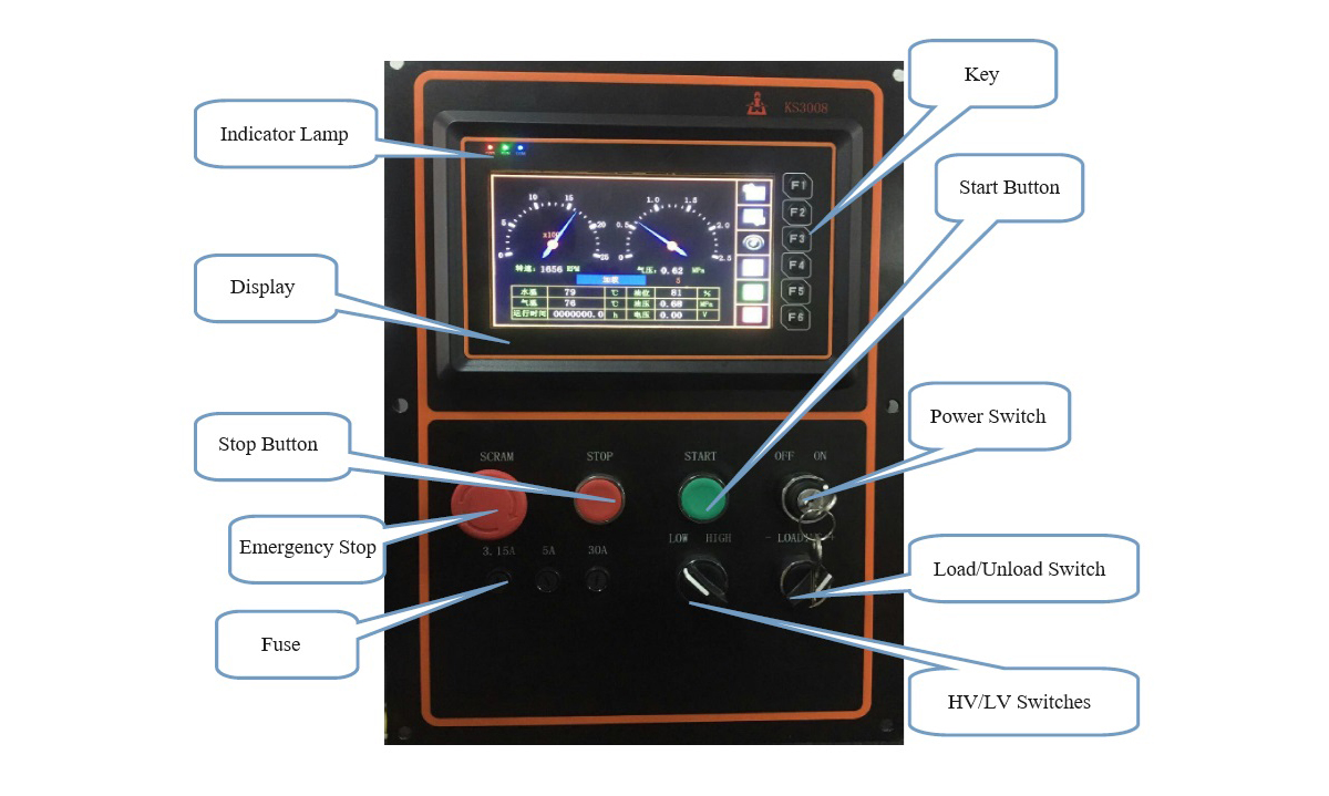
(1), Emergency stop: when an unexpected situation occurs, press down and then stop
immediately;
(2), stop: when pressed, the speed is reduced to idling speed, then stop the
machine;
(3), start: when pressed, start the machine and automatically disconnect the start relay
when the speed exceeds the
start speed;
(4), Load/Decrease: select the working state.
Chapter 3, Main Performance and Technical Parameters
For technical specifications, please visit the links below:
portable screw air compressor LGCY